PWM Input Capture handling. More...
#include "sarmfsw.h"
Data Structures | |
| struct | PWM_IC |
| PWM input capture structure. More... | |
Typedefs | |
| typedef struct PWM_IC | PWM_IC |
Functions | |
| GPIO_PinState | PWM_IC_get_Pin_State_Callback (const uint8_t idx) |
| PWM Input Capture get Pin state (in case of timeout, or at startup) | |
| FctERR | init_PWM_IC (PWM_IC *const pPWM_IC, TIM_HandleTypeDef *const pTim, const uint32_t Direct_Channel, const uint32_t Indirect_Channel, const uint32_t Scale) |
| Init PWM Input Capture channel. | |
| uint32_t | get_PWM_IC_Freq (PWM_IC *const pPWM_IC) |
| Get current PWM Input Capture frequency. | |
| uint32_t | get_PWM_IC_DutyCycle (PWM_IC *const pPWM_IC) |
| Get current PWM Input Capture duty cycle. | |
| void | PWM_IC_handler (void) |
| PWM Input Capture handler. | |
Variables | |
| PWM_IC | PWMin [1] |
Detailed Description
PWM Input Capture handling.
- Copyright
- MIT (c) 2017-2024, SMFSW
PWM_In configuration: TIM with multiple channels with slave mode capability shall be used
Slave Mode: Reset Mode Trigger: TI1FP1/TI2FP2 (depending physical MCU pin used tied to channel 1 or 2) Channel tied to pin: Input Capture direct mode Channel (2nd one): Input Capture indirect mode
Prescaler & CLK div: 0, No CLK div Counter Period: max possible value Counter Mode: Up Auto-Reload Preload: Disabled Trigger Output parameters: Disabled Input Capture Channel tied to pin: Rising Edge, Direct, No CLK div Input Capture Channel (2nd one): Falling Edge, Indirect, No CLK div
Instead, CubeMX Combined channels capture may be configured to PWM input capture, avoiding manual timer configuration
GPIO configuration: Alternate Function Push Pull ; Pull Up (if needed) ; High Speed may be recommended
NVIC configuration: Enable interrupt(s) if PWM_IC_NO_IT is not defined at project level
- Note
- Define NB_PWM_IC symbol with number of inputs at project level to use PWM_IC functionalities
- Define PWM_IC_NO_IT symbol at project level to disable TIM interrupts driven capture
- Warning
- Input Capture limitation:
- Lower/Higher frequency/duty cycle measurable totally depends on TIM configuration and clocks used.
- Continuous signal (pin held low or high) is detected automatically after timeout:
- automatically when using interrupts driven PWM input capture
- by calling PWM_IC_get_Pin_State_Callback without interrupts
- !!Please note there can be up to 1 second with startup timeout during which low to high continuous signal may be misinterpreted before retrieving values!!
- If PWM signal to capture can never become continuous, it may save some time of servicing interrupts to disable them (with PWM_IC_NO_IT symbol)
Typedef Documentation
◆ PWM_IC
| typedef struct PWM_IC PWM_IC |
Function Documentation
◆ get_PWM_IC_DutyCycle()
| uint32_t get_PWM_IC_DutyCycle | ( | PWM_IC *const | pPWM_IC | ) |
Get current PWM Input Capture duty cycle.
- Parameters
-
[in] pPWM_IC - pointer to PWM_IC instance
- Returns
- Measured duty cycle
◆ get_PWM_IC_Freq()
| uint32_t get_PWM_IC_Freq | ( | PWM_IC *const | pPWM_IC | ) |
Get current PWM Input Capture frequency.
- Parameters
-
[in] pPWM_IC - pointer to PWM_IC instance
- Returns
- Measured frequency
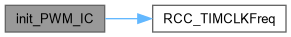
◆ init_PWM_IC()
| FctERR init_PWM_IC | ( | PWM_IC *const | pPWM_IC, |
| TIM_HandleTypeDef *const | pTim, | ||
| const uint32_t | Direct_Channel, | ||
| const uint32_t | Indirect_Channel, | ||
| const uint32_t | Scale ) |
Init PWM Input Capture channel.
- Parameters
-
[in,out] pPWM_IC - pointer to PWM input capture instance [in,out] pTim - pointer to TIM instance [in] Direct_Channel - Direct Channel used for PWM input capture [in] Indirect_Channel - Indirect Channel used for PWM input capture [in] Scale - PWM input capture duty cycle output scale
- Returns
- FctERR - Error code
◆ PWM_IC_get_Pin_State_Callback()
| GPIO_PinState PWM_IC_get_Pin_State_Callback | ( | const uint8_t | idx | ) |
PWM Input Capture get Pin state (in case of timeout, or at startup)
- Weak Functions
- Function declared as weak, needs to be customly implemented in user code, otherwise returns RESET state
- Parameters
-
[in] idx - PWM_IC instance index
- Returns
- Pin state
◆ PWM_IC_handler()
| void PWM_IC_handler | ( | void | ) |
PWM Input Capture handler.
- Note
- Shall to be called periodically if PWM_IC_NO_IT is defined
- When interrupts are used, handler can be called periodically (but not required), results getters will perform the conversion when required
Variable Documentation
◆ PWMin
|
extern |
Generated by